Запуск дисплея от часов на микросхеме lm8560 в Arduino
В данной статье рассматривается:
Дело было вечером, делать было нечего. А так как давно мучал вопрос, что в доме нет часов, чтоб те ходили относительно точно и их не надо было бы каждый раз подводить, то было решено достать старые китайские часы и их чуток модернизировать.
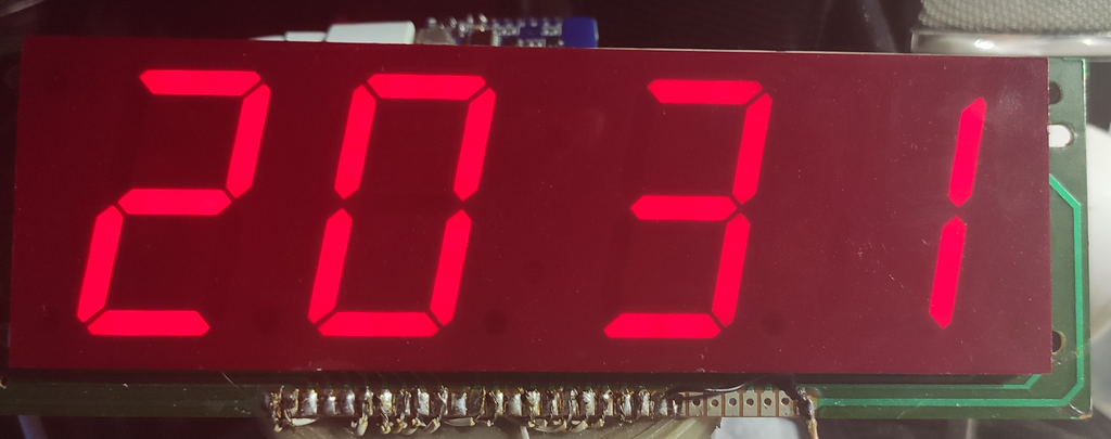
Вот наш дисплей уже в работе
Для запуска использовалось:
- WeMos D1 R2 на базе ESP8266 или LOLIN D1 mini
- Две микросхемы 74HC595N
- Дисплей – на самом дисплее непонятно что написано, но в точности соответствует LTC-637
- Всякая мелочевка, которую возьмем от тех же часов
Часы выполняю единственную функцию - показывают точное время. Часы периодически синхронизируются с сервером точного времени.
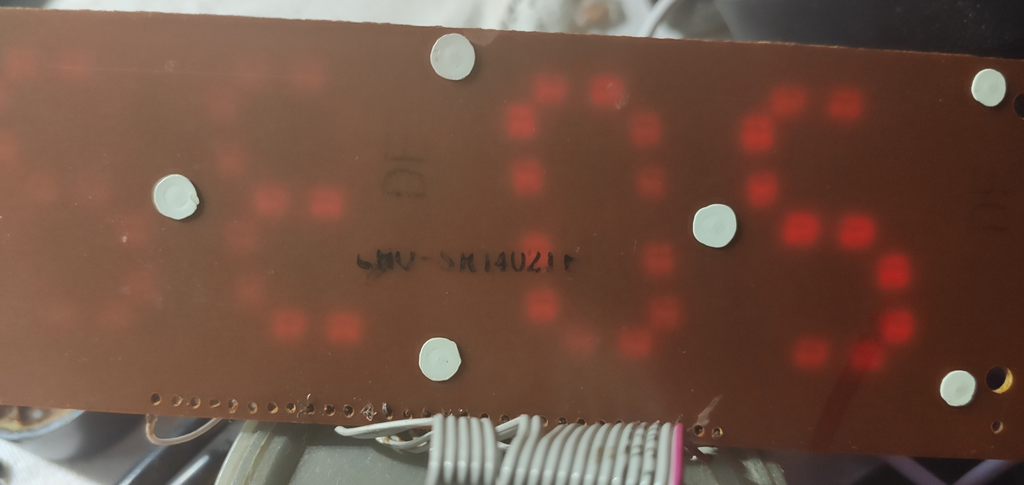
Процесс изучения распиновки, может кому пригодится.
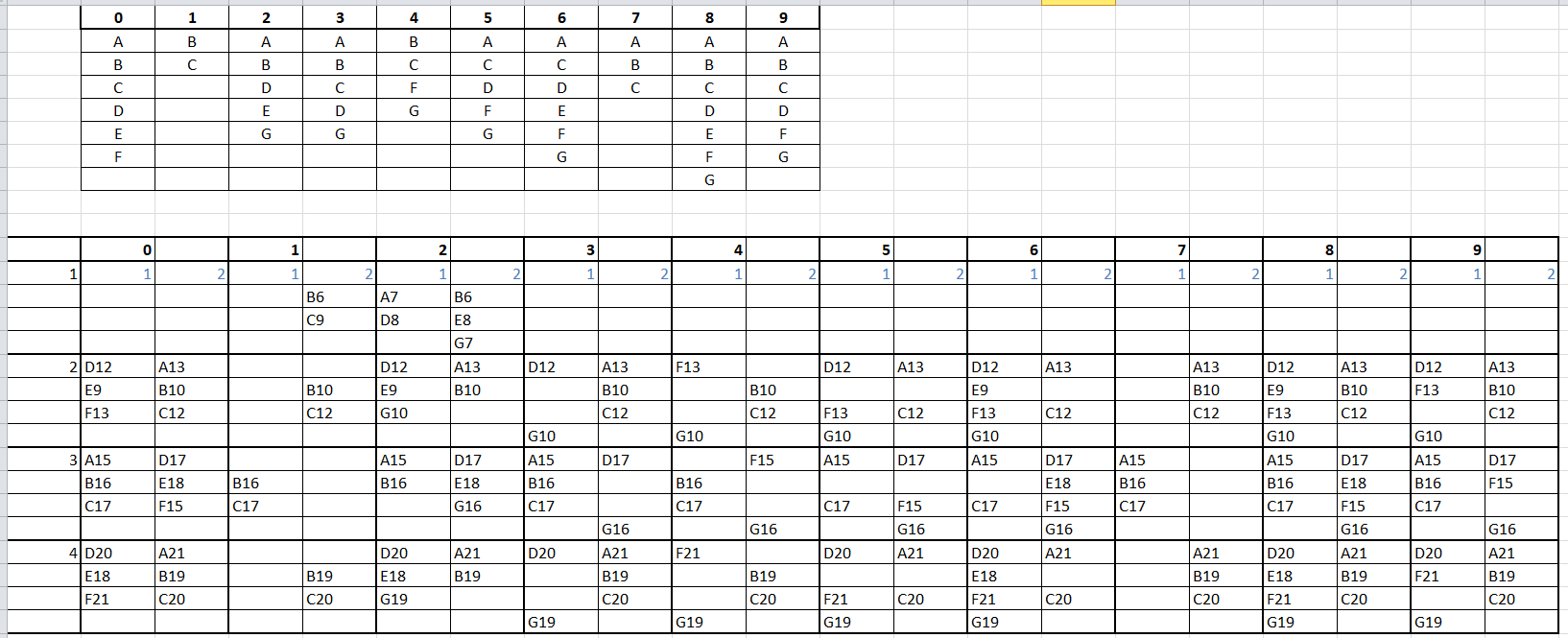
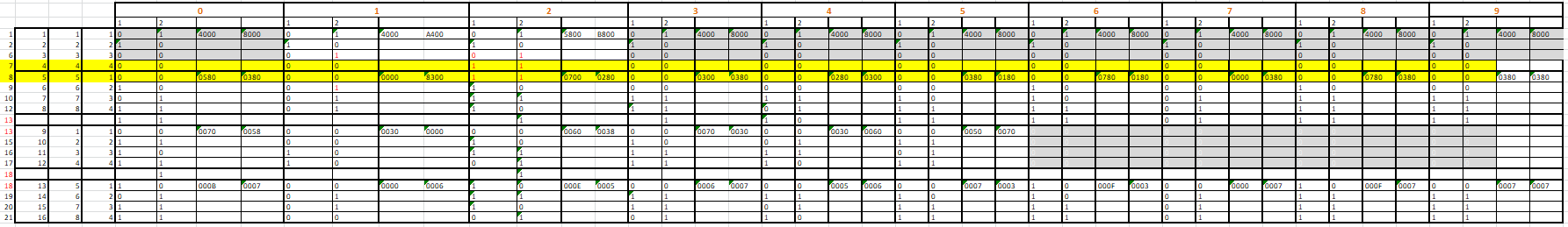
Схема подключения:
Рисуется.
Там все просто, первая нога 74HC595N на первую ножку дисплея LTC-637 и т.д. На ноги 1 и 2 ставим ограничительные резисторы 80Ом для ограничения тока. В итоге потребление одного сегмента около 5ма. Микросхема 74HC595N на одну ножку вытянет 25ма и на корпус 70ма. Что у нас с потребление дисплея 5*7*4= 140ма при работе «всех» сегментов. В каждый момент работает только половина: 70ма. 1 и 2 нога являются катодами для всех сегментов и через них проходит весь основной ток… Я делал часы из того что было и как можно быстрее. Простая переброска 2 ножки дисплея на вторую микросхему и пересчет кодов уже по нагрузке будет лучше. Чисто программно можно уменьшить нагрузку на микросхемы. Если подумать и делать по уму, то … я думаю вы сделаете как надо.
Данные на сдвиговые регистры передаются по SPI в основном цикле. Очень хотелось запустить DMA на SPI, но это отдельная тема для изучения. Если кто-то знает как, то поделитесь.
Код написан на коленке который надо дорабатывать и дорабатывать, и служит лишь примером.
/*
    SPI Master Demo Sketch
    Connect the SPI Master device to the following pins on the esp8266:

    GPIO    NodeMCU   Name  |   Uno
   ===================================
     15       D8       SS   |   D10
     13       D7      MOSI  |   D11
     12       D6      MISO  |   D12
     14       D5      SCK   |   D13

    Note: If the ESP is booting at a moment when the SPI Master has the Select line HIGH (deselected)
    the ESP8266 WILL FAIL to boot!
    See SPISlave_SafeMaster example for possible workaround


*/
#include "SPI.h"
#include "Ticker.h"

#include "ESP8266WiFi.h"
#include "WiFiUdp.h"


#ifndef STASSID
#define STASSID ""
#define STAPSK ""
#endif

#define UTC +3

const char* ssid = STASSID; // your network SSID (name)
const char* pass = STAPSK; // your network password

unsigned int localPort = 2390; // local port to listen for UDP packets

/* Don't hardwire the IP address or we won't get the benefits of the pool.
    Lookup the IP address for the host name instead */
//IPAddress timeServer(129, 6, 15, 28); // time.nist.gov NTP server
IPAddress timeServerIP; // time.nist.gov NTP server address
const char* ntpServerName[] = {"time.nist.gov","ntp5.stratum2.ru","2.europe.pool.ntp.org","time.windows.com"};

const int NTP_PACKET_SIZE = 48; // NTP time stamp is in the first 48 bytes of the message

byte packetBuffer[NTP_PACKET_SIZE]; //buffer to hold incoming and outgoing packets

// A UDP instance to let us send and receive packets over UDP
WiFiUDP udp;

uint16_t seg[2] = { 0, 0 };
int8_t hm[3] = {0, 0, 0 };

bool NtpSync=true;
bool NtpUpdate = true;
uint8_t ActiveNtpServer=0;

bool sw=true;

static const uint16_t digitSeg1[4][10] = { { 0x4000, 0x4000, 0x5800, 0x4000, 0x4000, 0x4000, 0x4000, 0x4000, 0x4000, 0x4000 },
    { 0x0580, 0x0000, 0x0700, 0x0300, 0x0280, 0x0380, 0x0780, 0x0000, 0x0780, 0x0380 },
    { 0x0070, 0x0030, 0x0060, 0x0070, 0x0030, 0x0050, 0x0000, 0x0000, 0x0000, 0x0000 },
    { 0x000B, 0x0000, 0x000E, 0x0006, 0x0005, 0x0007, 0x000F, 0x0000, 0x000F, 0x0007 } };

static const uint16_t digitSeg2[4][10] = { { 0x8000, 0xA400, 0xB800, 0x8000, 0x8000, 0x8000, 0x8000, 0x8000, 0x8000, 0x8000 },
    { 0x0380, 0x0300, 0x0280, 0x0380, 0x0300, 0x0180, 0x0180, 0x0380, 0x0380, 0x0380 },
    { 0x0058, 0x0000, 0x0038, 0x0030, 0x0060, 0x0070, 0x0000, 0x0000, 0x0000, 0x0000 },
    { 0x0007, 0x0006, 0x0005, 0x0007, 0x0006, 0x0003, 0x0003, 0x0007, 0x0007, 0x0007 } };


class ESPMaster
{
private:
    uint8_t _ss_pin;

public:
    ESPMaster(uint8_t pin)
        : _ss_pin(pin)
    {
    }
    void begin()
    {
        pinMode(_ss_pin, OUTPUT);
        digitalWrite(_ss_pin, HIGH);
    }

    void writeData(uint16_t data)
    {
        uint8_t first = data;
        uint8_t last = data >> 8;
        digitalWrite(_ss_pin, LOW);
        SPI.transfer(first);
        SPI.transfer(last);
        digitalWrite(_ss_pin, HIGH);
    }
};

ESPMaster esp(SS);

void ICACHE_RAM_ATTR onTimerISR()
{

    if (hm[2] < 59) {
        hm[2]++;
    }
    else {

        hm[2] = 0;

if(!NtpSync){

  NtpSync=true;

  if(ActiveNtpServer>=3)
  {
    ActiveNtpServer=0;

  }else  { ActiveNtpServer++; }

  NtpUpdate = true;

  }
        if (hm[1] < 59) {
            hm[1]++;
        }
        else {

            hm[1] = 0;

            if (hm[0] < 23) {

                hm[0]++;
            }
            else {

                hm[0] = 0;

                NtpUpdate = true;
            }
        }

        setLCD();

    }

    Serial.print(hm[0]);
    Serial.print(":");
    Serial.print(hm[1]);
    Serial.print(":");
    Serial.print(hm[2]);
    Serial.println();

if(sw) { sw = false;
digitalWrite(D0, HIGH);
}
else { sw = true;
digitalWrite(D0, LOW);
}

    //timer1_write(4999628);
    timer1_write(5000000);
}

void setup()
{
    Serial.begin(115200);
    SPI.begin();
    SPI.setClockDivider(SPI_CLOCK_DIV2);
    SPI.setBitOrder(LSBFIRST);
    esp.begin();

    esp.writeData(0);
    esp.writeData(0);

    pinMode(D0, OUTPUT);
    digitalWrite(D0, LOW);

    setupNTP();

    timer1_attachInterrupt(onTimerISR);
    timer1_enable(TIM_DIV16, TIM_EDGE, TIM_SINGLE);
    timer1_write(1200000);

    setLCD();
}

void setLCD()
{

    uint8_t d1 = hm[0] / 10;
    uint8_t d2 = hm[0] % 10;
    uint8_t d3 = hm[1] / 10;
    uint8_t d4 = hm[1] % 10;

    seg[0] = digitSeg1[0][d1] | digitSeg1[1][d2] | digitSeg1[2][d3] | digitSeg1[3][d4];
    seg[1] = digitSeg2[0][d1] | digitSeg2[1][d2] | digitSeg2[2][d3] | digitSeg2[3][d4];
}

void setupNTP()
{
    Serial.println();
    Serial.println();

    // We start by connecting to a WiFi network
    Serial.print("Connecting to ");
    Serial.println(ssid);
    WiFi.mode(WIFI_STA);
    WiFi.begin(ssid, pass);

    while (WiFi.status() != WL_CONNECTED) {
        delay(500);
        Serial.print(".");
    }
    Serial.println("");

    Serial.println("WiFi connected");
    Serial.println("IP address: ");
    Serial.println(WiFi.localIP());

    Serial.println("Starting UDP");
    udp.begin(localPort);
    Serial.print("Local port: ");
    Serial.println(udp.localPort());

  //  getTimeNTP();
}

void loop()
{

    esp.writeData(seg[0]);
    esp.writeData(seg[1]);

    if(NtpUpdate)
    {
    getTimeNTP();
    NtpUpdate = false;
    }

}

void getTimeNTP()
{

    esp.writeData(0);
    esp.writeData(0);

    WiFi.hostByName(ntpServerName[ActiveNtpServer], timeServerIP);

    sendNTPpacket(timeServerIP); // send an NTP packet to a time server
    // wait to see if a reply is available
    delay(1000);

    int cb = udp.parsePacket();
    if (!cb) {
        Serial.print(ntpServerName[ActiveNtpServer]);
        Serial.print(" IP:");
        Serial.print(timeServerIP);
        Serial.println(" - no packet yet!");
        NtpSync = false;
    }
    else {
        Serial.print(ntpServerName[ActiveNtpServer]);
        Serial.print(" - packet received, length=");

        Serial.println(cb);
        // We've received a packet, read the data from it
        udp.read(packetBuffer, NTP_PACKET_SIZE); // read the packet into the buffer

        //the timestamp starts at byte 40 of the received packet and is four bytes,
        // or two words, long. First, esxtract the two words:

        unsigned long highWord = word(packetBuffer[40], packetBuffer[41]);
        unsigned long lowWord = word(packetBuffer[42], packetBuffer[43]);
        // combine the four bytes (two words) into a long integer
        // this is NTP time (seconds since Jan 1 1900):
        unsigned long secsSince1900 = highWord << 16 | lowWord;

        // Unix time starts on Jan 1 1970. In seconds, that's 2208988800:
        const unsigned long seventyYears = 2208988800UL;
        // subtract seventy years:
        unsigned long epoch = secsSince1900 - seventyYears;

        hm[0] = ((epoch % 86400L) / 3600);
        hm[1] = ((epoch % 3600) / 60);
        hm[2] = epoch % 60;

        if (hm[0] > 20) {
            hm[0] = UTC - (24 - hm[0]);
        }
        else {
            hm[0] += 3;
        }

        // print the hour, minute and second:
        Serial.print("The +3 time is "); // UTC is the time at Greenwich Meridian (GMT)
        Serial.print(hm[0]); // print the hour (86400 equals secs per day)
        Serial.print(':');
        if (hm[1] < 10) {
            // In the first 10 minutes of each hour, we'll want a leading '0'
            Serial.print('0');
        }
        Serial.print(hm[1]); // print the minute (3600 equals secs per minute)
        Serial.println();
        setLCD();
    }

}

// send an NTP request to the time server at the given address
void sendNTPpacket(IPAddress& address)
{
    Serial.println("sending NTP packet...");
    // set all bytes in the buffer to 0
    memset(packetBuffer, 0, NTP_PACKET_SIZE);
    // Initialize values needed to form NTP request
    // (see URL above for details on the packets)
    packetBuffer[0] = 0b11100011; // LI, Version, Mode
    packetBuffer[1] = 0; // Stratum, or type of clock
    packetBuffer[2] = 6; // Polling Interval
    packetBuffer[3] = 0xEC; // Peer Clock Precision
    // 8 bytes of zero for Root Delay & Root Dispersion
    packetBuffer[12] = 49;
    packetBuffer[13] = 0x4E;
    packetBuffer[14] = 49;
    packetBuffer[15] = 52;

    // all NTP fields have been given values, now
    // you can send a packet requesting a timestamp:
    udp.beginPacket(address, 123); //NTP requests are to port 123
    udp.write(packetBuffer, NTP_PACKET_SIZE);
    udp.endPacket();
}
Комментариев: 4
Александр
Ты в самом деле сделал на 74HC95N?
Может все таки на 74HC595?
Admin
Опечатался, конечно, на сдвиговом регистре 74HC595
Александр
Спасибо за быстрый ответ!
Еще не понял по подключению, в статье у вас написано 1, 2 итд, значит у нас первыми идут именно катоды? т.е. как у LTC-637 по очереди без изменений.
Никогда не использовал spi для подключения этой микросхемы (только 3 пина), а тут 4 в скетче .
Разобрался где что на микросхеме, если все правильно понял получается:
mosi (dio) - 14
ss (rclk) - 12
sck (sclk) - 11
miso (dh) - 9
Но, у нас 9 нога первой микросхемы должна идти на 14 Я так понимаю это мусор от библиотеки и мы используем 3 пина?
И можем ли мы после этого использовать 14 gpio на esp для других целей?
Александр
Сам не понял себя)
У нас с 9 нога с первой идет на 14 второй микрухи.
И не gipio 14 а gpio 12 d6 он же miso хотел сказать